There are numerous guides to controlling a 4 pin PC fan with an Arduino and ESP32. None of them worked to read the tachometer correctly for me with a Noctua NF12 fan. The issue is that the spec for the tachometer (Pin 3) is that it be pulled up to 12 Volts with a maximum current of 5mA. This is the Reference for this from Intel, you will find the 12Volt requirement at the start of section 2. We need the tachometer of the fan to a. see close to 12V and b. the ESP32 to see 3.3V.
Some guides suggest you can directly connect the tachometer to a GPIO pin of the ESP32 and use INPUT_PULLUP. That only works with 5V fans that will be using 5V tachometer logic and that is pushing the diode of the ESP32 to its limit, even 5V fans should use a 3 resistor pair of voltage dividers as we see below, only with different values. I have also seen a simple voltage divider with 10k and 4.7k resistors suggested which would produce a voltage in the middle of 3.8 Volts, but this doesn’t meet the fans need for 12V nor the ESP32’s need for 3.3V and it also didn’t work.
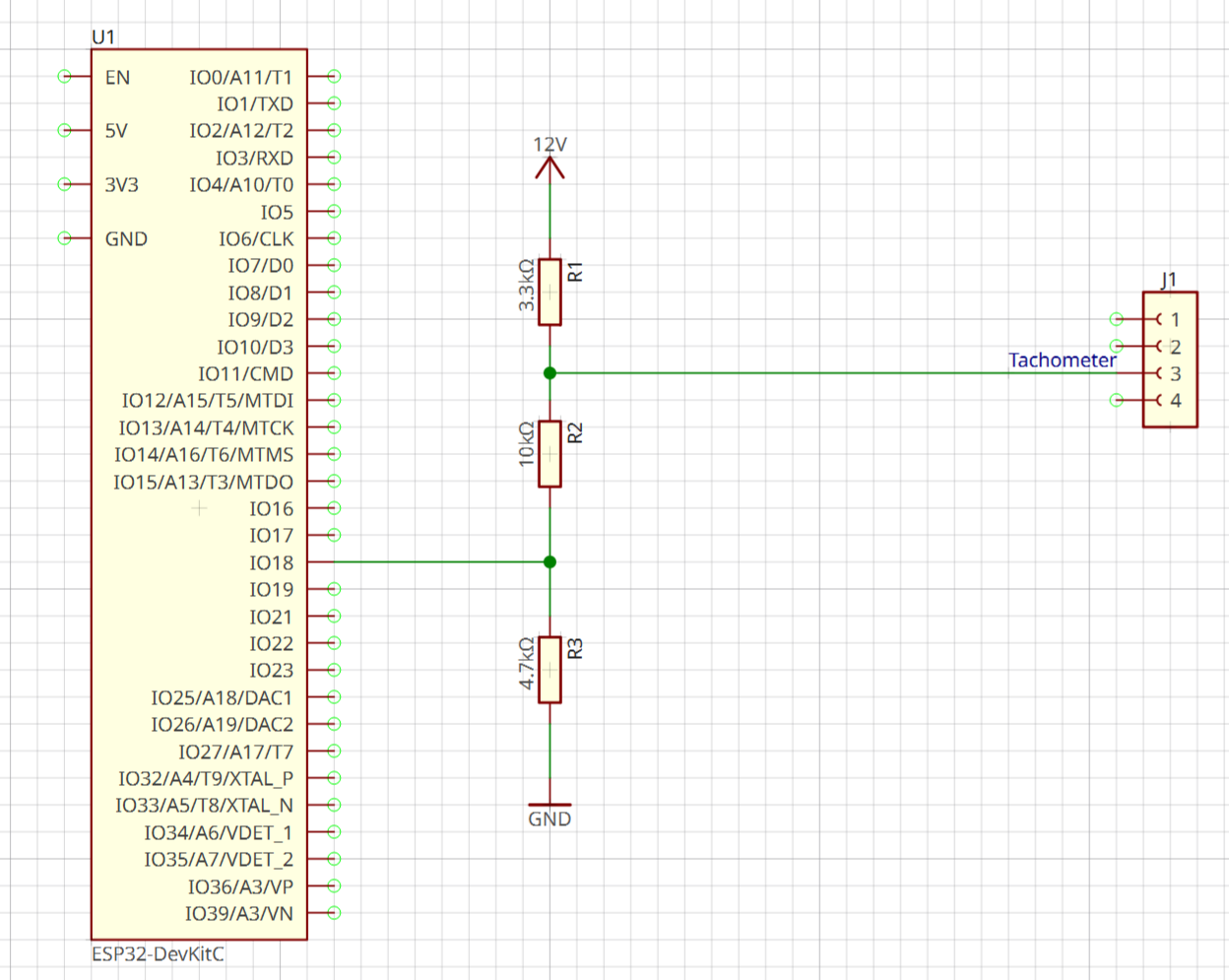
Without going to a level shifter the only thing we can really do is a pair of voltage dividers, or 3 resistors in series from the 12V down to Ground and use two different levels to select the voltage each device sees. The image below shows the setup I have had success with on a variety of 12V PC fans. The fan tachometer sees 9.8V (the voltage division being between 3.3KOhm and 14.7KOhm) and the ESP32 GPIO pin sees 3.1 V as its division is between 12.3KOhm and 4.7KOhm.
These are not the ideal resistor values its what I have to hand and which are reasoably available. Something better but impossible to buy would minimise the resistance of R1 to 2.2KOhm. Then R2 would be 36kOhm and finally R3 14.5KOhm. This would put the ESP32 voltage at 3.3 and the tachometer at 11.5V. I don’t know what the PC motherboard manufacturers are actually doing to interface with the tachometers and it would be nice to know. Its possible to also get 12V to 3.3V level shifters which would do this quite neatly and expensively without the need for voltage division.
A small note on the PWM input on pin 4. The PWM is a normal 3.3-5 V tolerant logic connection with 25000 hz pulses so that can be directly connected to the ESP32 and a 5V arduino. The reason for the 25,000 hz is to ideally put the impact of this noise on the fan beyond human hearing its not an actual requirement of the interface but its a good idea to follow it to avoid noise.
It took me a lot longer than it should have done to work through all the various options and come to the conclusion I have to make something that actually works. If your tachometer signal is producing garbage numbers or worse appears to be roughly 2x the 25,000 PWM signal then I suggest using 3 resistors like this and setting up a pair of voltage dividers, this works reliably and it protects the ESP32 GPIOs from excess voltage.